June 19, 2021
2758
Audio systems are designed to receive audio signals (via microphones), record audio in some storage, transmit audio (via wired or wireless communication channels) and reproduce audio signals (via speakers). Therefore, audio circuits perform signal processing to represent sound in the form of electrical signals, manipulate electrical (audio) signals, such as amplify, filter or mix, reproduce sounds from audio signals, store audio in computer files, or reproduce audio from them. Audio files. The following block diagram can represent a general audio system.
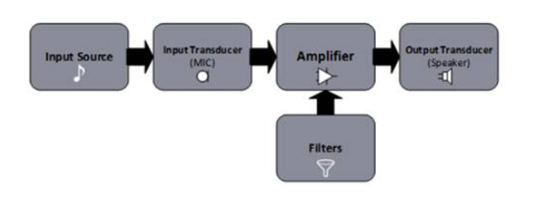
Figure 1. Block diagram of the audio system
Like microphones, audio sources and speakers, audio filters are also a basic part of an audio system. Audio filters are actually amplifiers or passive circuits with different frequency responses. They can amplify or attenuate the frequency range of the audio input. This is different from simple audio amplifiers or input sources, which do not have frequency-related functions. Any simple audio amplifier will amplify the complete input audio signal regardless of its frequency, or the audio source will transmit the audio signal regardless of the frequency in the signal.
By amplifying or attenuating a specific frequency range in the audio signal, the audio input tone can be creatively enhanced. Audio frequency dividers and equalizers are also types of audio filters. An audio crossover is an electronic filter used to divide the audio input signal into different frequency ranges to be sent to different drivers (treble, midrange and woofer). An audio equalizer is an electronic filter used to amplify audio signals based on frequency-related functions. Therefore, for different frequencies, the output of the equalizer has different amplification levels. Crossovers and equalizers play a major role in audio equipment. In this tutorial, we will discuss different types of filters and the terms related to them.
What is an audio filter?
An audio filter is an electronic circuit designed to amplify or attenuate a certain range of frequency components. This helps to eliminate harmful noise in the audio signal and improve the tone of the audio output. Filters play an important role in the fields of telecommunications and electronic audio.
Filter type
A filter is a special type of amplifier or passive circuit with a frequency-dependent output. Filters can be classified in a variety of ways, such as construction, frequency response, or both.
According to the structure, audio filters are divided into the following categories:
1) Passive filter
2) Active filter
The terms "passive" and "active" are often used in this context for electronic components. Components that require power for operation are called active components, such as transistors and OPAMs. Those electronic components that do not need any power source to work are called passive components, such as resistors, capacitors, and inductors.
Passive filter: It is designed using passive components such as resistors and capacitors or resistors and inductors. The impedance of capacitors and inductors depends on the frequency, which allows the use of resistors/capacitors, resistors/inductors or resistor/capacitor/inductor combinations to construct filters. These filters do not require any power to operate, which is why they are called passive filters.
Active filters: Active filters are designed using active components such as transistors or operational amplifiers. The transistor or operational amplifier requires a DC power supply for bias. By using active components, there is no need to use inductors to build filters. This reduces the size and cost of the circuit, and improves the efficiency of the filter. Since the active components of these filters require a DC bias source, they are called active filters.
Filters can also be classified according to their frequency response. The frequency range that the filter is amplified or allowed to pass is called the passband. The passband is the area where the voltage or power of the circuit in the filter frequency curve is the greatest. According to the frequency band allowed by the filter, it is classified as follows:
1) High pass filter
2) Low pass filter
3) Band pass filter
4) Band stop filter
5) Notch filter
6) All-pass filter
7) Equalization filter
High-pass filter: This filter passes all frequencies higher than its cut-off frequency and blocks all frequencies lower than its cut-off frequency. The cut-off frequency refers to the cut-off frequency when the voltage or amplitude of the signal drops to 0.707 or 3 dB of the pass-band voltage. At this time, the power output of the circuit begins to drop, and the typical frequency curve of the high-pass filter is shown below.
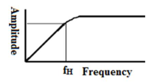
Figure 2: This figure shows the frequency response of a high-pass audio filter
It can be seen from the frequency response graph that the low-frequency signal will not be completely attenuated at the cut-off frequency. Frequencies below the cutoff frequency are also passed through the high-pass filter, but the gain is small. Therefore, the cutoff frequency will drop. This is why it is sometimes referred to as the roll-down frequency.
Low-pass filter: This filter passes all frequencies lower than its cut-off frequency and blocks frequencies higher than its cut-off frequency. The frequency response of the low-pass filter is as follows:
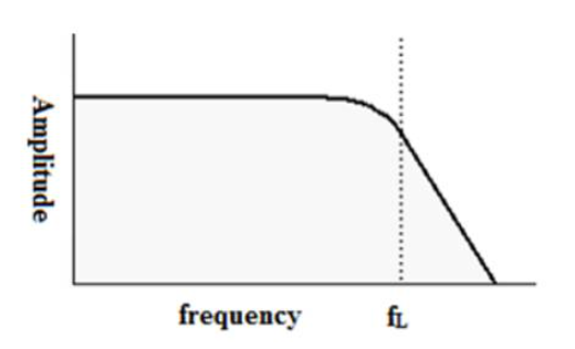
Figure 3: This figure shows the frequency response of a low-pass audio filter
It can be seen from the frequency response graph that the high-frequency signal is not completely attenuated at the cut-off frequency. The frequencies above the cutoff frequency are also passed through the low-pass filter, but the gain is very small.
Band pass filter: This filter only passes the frequency band within the cut-off frequency range. Bandpass filters have two cutoff frequencies, one is a lower cutoff frequency, and the other is a higher cutoff frequency. The center frequency and bandwidth of the filter determine the frequency response below, as shown in the lower limit and upper limit frequency.
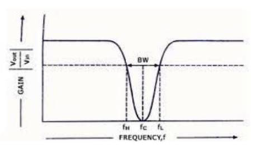
Figure 4: This figure shows the frequency response of a band-stop audio filter
Band stop filter: The band stop filter can pass all frequencies except the specific frequency range. It passes all frequencies below its lower limit and all frequencies above its upper limit, but does not pass frequencies between the upper and lower limits. The higher cut-off frequency and the lower cut-off frequency are deviations from the center frequency, for which the gain of the filter circuit is ideally zero (in fact the smallest).
Notch filter: A notch filter is a band stop filter with a very narrow stop band. Because the stopband is very narrow, these filters have a very high quality factor.
All-pass filter: The all-pass filter allows all frequencies to pass, but modifies the phase relationship between them. Therefore, at the output of the all-pass filter, different frequency ranges have phase differences with each other. The frequency response graph of the all-pass filter has a phase shifted frequency, as shown in the figure below.
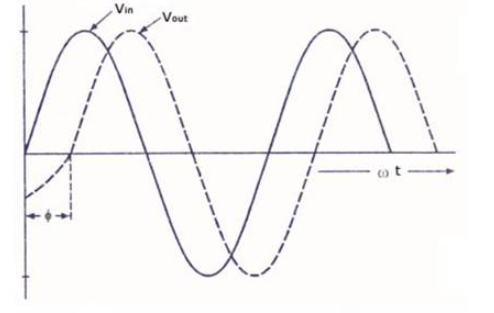
Figure 5: This figure shows the phase-shifted frequency response of an all-pass audio filter
Equalizer filter-The equalizer filter does not completely attenuate or pass a specific range of frequencies, but variably amplifies frequencies according to a frequency-dependent function.
Based on frequency response and structure, filters can be divided into the following categories:
1) Passive high pass filter
2) Active high pass filter
3) Passive low-pass filter
4) Active low-pass filter
5) Passive band pass filter
6) Active band pass filter
7) Passive band stop filter
8) Active band stop filter
Passive high-pass filter: The high-pass filter blocks lower frequency components and allows higher frequency components. A passive high-pass filter can be constructed using an RC network. This type of filter is usually used to direct the high frequency components of the audio signal to the tweeter. A simple passive high-pass filter is shown below.
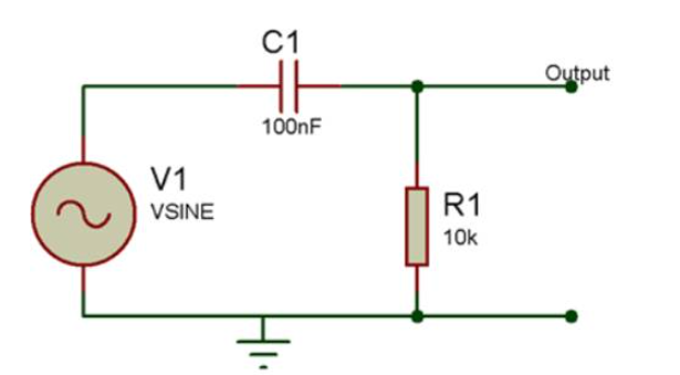
Figure 6: Circuit diagram of a first-order passive high-pass audio filter
For the RC network shown above, the cutoff frequency is related to the resistance and capacitor, as shown below:
fh = 1 /(2πRC)
Therefore, by setting the value of the resistor and capacitor, a high-pass filter with a desired cut-off frequency can be designed. In the above circuit, the cut-off frequency is about 160 Hz. The high pass filter above will pass all frequencies above 160 Hz and attenuate frequencies below it.
Passive filters have no bandwidth limitation, and can be designed by choosing appropriate values of resistors and capacitors. It does not require any power supply for DC bias. Such a filter requires fewer components to design and has a high current output. However, these filters cannot amplify audio signals, and if inductors are used to construct them, they are expensive and bulky.
Active high-pass filter: You can use transistors or operational amplifiers to design active high-pass filters. A simple active high-pass filter (first-order filter) is as follows:
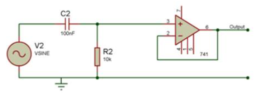
Figure 7: Circuit diagram of a first-order active high-pass audio filter
The filter uses OPAM (operational amplifier) at the output of the RC network to make it an active filter. When the RC network blocks low frequency components, OPAM will amplify the permitted frequency range. Since the RC network is connected to the non-inverting input pin of the operational amplifier, its output will not be inverted. However, if you connect it to the inverting pin of OPAM, the audio signal output will be 180 degrees out of phase with the audio signal input.
This filter has no loading effect. OPAM has high input impedance and low output impedance, so they are not affected by the source and load. The filter has a non-unity gain and is usually very high. Therefore, the audio signal output is not only noise-free, but can also be amplified. The size of these filters is also small, and generally, the ICs or transistors used in their designs are not bulky. However, the active filter design involves more components, and the biasing of these components requires a DC power supply. Therefore, the filter circuit needs an external power supply to work. Moreover, due to the use of operational amplifiers, the filter circuit has bandwidth limitations.
Passive low-pass filter: RC network or RL network (for first-order filters) can be used to construct a passive low-pass filter. The RLC network can be used to construct a second-order low-pass filter. By connecting many first-order filters in series, a high-order low-pass filter that can filter audio signals more accurately can be designed. In a simple passive low-pass filter, the input audio signal passes through a resistor (rather than a capacitor like in a high-pass filter). The capacitor is connected between the resistor and ground.
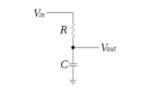
Figure 8: The circuit diagram of the first-order passive low-pass audio filter
The following formula gives the cutoff frequency of the filter:
fl = 1 /(2πRC)
The filter allows all frequencies below the cutoff frequency to pass, but attenuates frequencies above the cutoff frequency. These filters do not have any bandwidth limitations and do not require any power supply to operate. These are usually used to drive the low frequency components of the audio signal to the woofer.
Active low-pass filter: Active low-pass filter uses operational amplifiers or transistor amplifiers at the output before low-pass RC, RL, RLC or multi-stage passive filters. The operational amplifier amplifies the allowable low-frequency components before transmitting to the power amplifier or speaker. The gain provided by OPAM is the main advantage of this filter. However, such filters have bandwidth limitations and require DC sources for biasing OPAM or transistor circuits.
Passive band-pass filter: The band-pass filter is designed by combining low-pass and high-pass filters. It is usually constructed using RLC networks. A simple passive bandpass filter is shown below.
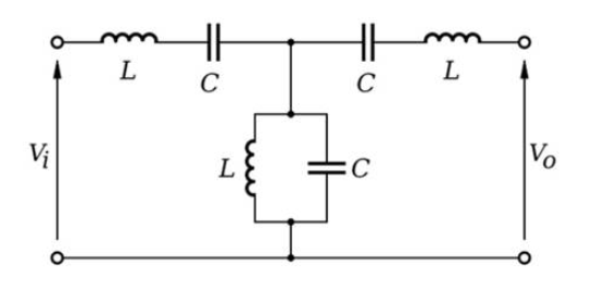
Figure 9: Circuit diagram of a first-order passive band-pass audio filter
In the band-pass filter shown above, the high-pass filter and the low-pass filter are connected in series. The cut-off frequency of the high-pass filter is actually the lower cut-off frequency of the band-pass filter. The cut-off frequency of the low-pass filter is actually the higher cut-off frequency of the band-pass filter. Therefore, only the frequencies between the frequency tangents of the combined high-pass and low-pass filters are allowed to pass through the output.
These filters are usually used to direct a certain range of frequencies to mid-range drives. Due to the increase in the number of components in the construction, the size of these filters is very large.
Active bandpass filter: The operational amplifier or transistor amplifier of the active bandpass filter is connected before the output after the passive bandpass circuit. The operational amplifier amplifies the allowable frequency band. In this filter, the bandwidth of the OPAM must match the desired bandwidth of the bandpass filter.
Passive band stop filter: The band stop filter attenuates a certain range of frequencies and allows the pass frequency to be lower than its lower cut-off frequency and higher than its higher cut-off frequency. The (first-order) passive band-stop filter is usually constructed using an RLC network, where the input signal is passed through a resistor. The LC network is connected between the resistor and ground. A simple passive bandpass filter is shown below.
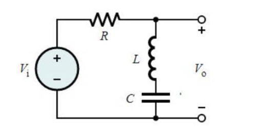
Figure 10: Circuit diagram of a first-order passive band-stop audio filter
Such a circuit is a parallel combination of high-pass and low-pass filters. The cut-off frequency of the high-pass filter is the higher cut-off frequency of the band rejection filter, and the cut-off frequency of the low-pass filter is the lower cut-off frequency of the band rejection filter. Therefore, only frequencies that do not include frequencies between the cutoff frequencies of the combined high-pass and low-pass filters are allowed to pass at the output. These filters are also called band stop filters, band stop filters and T notch filters.
Active band stop filter: The output of the active band stop filter has an operational amplifier or transistor amplifier, which is used to amplify the allowable frequency signals, and then pass them to the power amplifier or audio driver. OPAM using this type of amplifier must have a suitable bandwidth to match the desired frequency curve of the band-stop filter.
The terminology is rarely used in the context of audio filters. Some of these terms will be explained below.
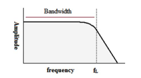
1) Bandwidth: This is the frequency range allowed by the filter. Bandwidth can be defined as the difference between the upper and lower cutoff frequencies. Sometimes called "passband bandwidth". The bandwidth determines the frequency range of the frequency response of the filters in the filter bank. The figure below shows the bandwidth of the frequency response curve of the low-pass filter.
