January 30, 2024
2785
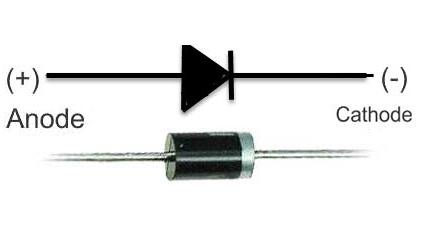
Rectifier diodes play a pivotal role in the field of electronics, serving as fundamental components in power supply circuits. These diodes are essential for converting alternating current (AC) to direct current (DC), a process integral to powering a myriad of electronic devices. Understanding their definition, symbols, circuit configurations, uses, types, and characteristics is key to comprehending their widespread application in various industries.
A rectifier diode, also known simply as a rectifier, is a crucial electronic component designed to rectify alternating current (AC) into direct current (DC). Its primary function is to allow the flow of current in one direction while blocking it in the opposite direction. This conversion from AC to DC is vital for numerous electronic devices and power supply applications.
Rectifier diodes are typically constructed using semiconductor materials, with silicon being the most common choice due to its excellent electrical properties. These diodes come in various types, including but not limited to standard silicon rectifiers and Schottky diodes.
In half-wave rectification, only one half of the AC waveform is allowed to pass through, resulting in pulsating DC. This is achieved using a single rectifier diode.
Full-wave rectification uses a combination of diodes to allow both halves of the AC waveform to contribute to the DC output, resulting in a smoother DC signal.
Bridge rectifiers are a common configuration using four diodes arranged in a bridge circuit. This arrangement allows for efficient full-wave rectification and is widely used in power supply circuits.
Schottky rectifier diodes are known for their fast switching capabilities and lower forward voltage drop compared to standard silicon diodes. They are often employed in high-frequency applications and digital circuits.
Rectifier diodes come in a wide range of current and voltage ratings to suit various applications. They can handle currents ranging from milliamperes (mA) to several kiloamperes (KA) and voltages from several volts to several kilovolts (KV).
Rectifier diodes find applications in power supplies, battery chargers, inverters, and many electronic devices that require DC power. They play a crucial role in converting the AC power from the electrical grid into the DC power needed for electronic circuits.
The junction temperature of a rectifier diode is a critical factor in its performance. Excessive temperatures can affect the diode's efficiency and lifespan. Heat sinks or other cooling mechanisms are often employed to maintain optimal operating conditions.
A diode is a semiconductor device with two terminals that permits the flow of current in one direction while blocking it in the opposite direction. In electronic circuits, diodes function as switches. On the other hand, a rectifier is a device employed to convert alternating current (AC) into direct current (DC). The rectifier achieves this conversion through the utilization of diodes, a step-down transformer, and a filter circuit.
Diodes serve a crucial role in electronic circuits, functioning as semiconductor devices that allow current to flow when forward biased, while effectively blocking current in the reverse-biased state. Despite their relatively lower current-carrying capability, diodes are indispensable components in a variety of electronic applications, serving purposes such as switches, clampers, and clippers. Noteworthy is the existence of various diode types, such as Zener diodes and photodiodes, each tailored to specific functionalities.
In electrical systems, rectifiers play a pivotal role in converting alternating current (AC) to direct current (DC). Comprising a diode, a step-down transformer, and a filter circuit, rectifiers collectively facilitate this conversion process. In comparison to a standalone diode, a rectifier boasts a higher current-carrying capacity, making it well-suited for applications demanding greater power. Devices like computers and batteries extensively employ rectifiers, meeting the need for a stable and reliable source of DC power. Rectifiers are further categorized into single-phase and three-phase types, with single-phase rectifiers branching into half-wave and full-wave rectifiers, each designed for specific electrical system requirements.
While a diode primarily serves as a current-directional device, a rectifier encompasses a broader functionality, specifically geared towards the conversion of alternating current to direct current. Rectifiers play a crucial role in various electronic systems, offering a higher current-handling capacity compared to standard diodes.
As a Rectifier diode is essentially a PN junction diode, its symbolic representation becomes crucial for understanding its functionality within an electrical circuit. The symbolic depiction of a Rectifier diode takes the form of a triangle pointing towards a straight line. This visual representation serves as a concise guide, illustrating the direction in which the diode permits the flow of current—specifically, towards the straight line.
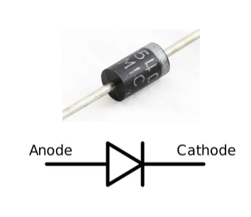
Within this symbolic representation, the base of the triangle holds significant meaning, as it denotes the Anode or the positive terminal of the diode. Conversely, the straight line emanating from the triangle signifies the Cathode, representing the negative terminal. This symbolic language aids engineers, technicians, and enthusiasts in quickly grasping the orientation and behavior of the Rectifier diode in a circuit.
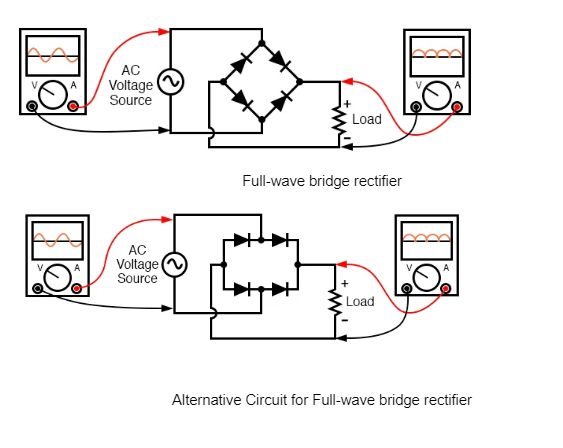
Full-wave bridge rectifier
Alternative Circuit for Full-wave bridge rectifier
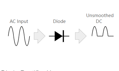
A diode serves the fundamental purpose of permitting the flow of electric current in a singular direction. The process of rectification involves the application of an alternating current (AC) waveform to the diode. In this context, a rectifier diode plays a crucial role by allowing the conduction of more than half of the AC waveform while blocking the remaining portion. This selective conductivity is the essence of rectification achieved through the rectifier diode.
To visualize this rectifying action more intuitively, refer to the accompanying image below. The graphical representation vividly illustrates how the rectifier diode facilitates the flow of current during specific intervals of the AC waveform, effectively directing it in a unidirectional manner. This graphical aid enhances our understanding of the rectification process, making it more accessible and comprehensible.
Diode rectifiers find widespread applications in various electronic and electrical systems due to their ability to convert alternating current (AC) to direct current (DC).
Power Supplies
Diode rectifiers are fundamental components in power supply units, converting the incoming AC voltage from the electrical grid into a stable DC voltage. This is crucial for powering electronic devices and systems that require a consistent and unidirectional power source.
Battery Charging
In battery charging systems, diode rectifiers are employed to convert AC power to DC, which is then used to charge rechargeable batteries. This application is common in devices ranging from small electronic gadgets to electric vehicles.
Electronics
Diode rectifiers are utilized in electronic circuits for various purposes, including signal demodulation, where they convert amplitude-modulated (AM) signals back into their original form by rectifying the carrier wave.
Audio Systems
Rectifiers are used in audio systems to convert the AC signal from a microphone or audio input source into a pulsating DC signal. This rectified signal is then smoothed using capacitors to remove the pulsations, providing a cleaner DC voltage for amplification.
Telecommunications
Diode rectifiers play a role in telecommunications systems, where they are used in rectifying AC signals to provide the necessary DC voltage for powering components such as transmitters and receivers.
Industrial Applications
In industrial settings, diode rectifiers are employed in various equipment and machinery where a stable DC power source is required for control circuits and electronic components.
Photovoltaic Systems
In solar power systems, diode rectifiers are used to convert the DC power generated by solar panels into a form suitable for use or storage. This ensures efficient utilization of solar energy in both residential and commercial applications.
LED Lighting
Diode rectifiers are used in LED lighting systems to convert AC power to the DC power required to illuminate the LEDs. This is essential for ensuring the longevity and proper functioning of LED lights.
Automotive Systems
In automotive electronics, diode rectifiers are employed in alternators to convert the AC output from the alternator into DC power for charging the vehicle's battery and powering various electrical systems.
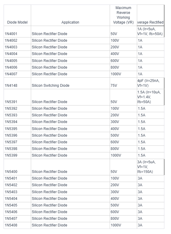
Bridge rectifier circuits exhibit diversity in their types, primarily distinguished by the supply voltage structure, the number of phases, and various half-wave rectification voltages. In terms of supply voltage and phases, one encounters single-phase bridge rectifier circuits and their multi-phase counterparts, including three-phase and two-phase configurations. Additionally, the rectification voltage varies, encompassing single bridge (half-wave rectification) and double bridge (full-wave diode rectification) setups. The versatility extends to combination circuits, enabling the creation of single-phase full-wave bridge rectifiers or three-phase full-wave rectifiers, integrating the number of phases with either full-wave or half-wave rectification.
The half-wave bridge rectifier circuit stands out as the most straightforward design for transforming alternating current, characterized by two signs, + and -, into a unidirectional current with a single sign (+). Once the resulting output current undergoes additional filtering, it can be effectively converted into direct current (DC).
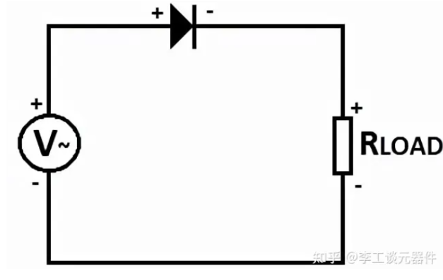
At the output stage of this circuit, a sine wave featuring solely the positive half period emerges, leading to its nomenclature as a half-wave rectifier. The rationale behind this nomenclature lies in the fact that the rectifier diode conducts exclusively when forward biased, allowing current to flow pulsatingly through a resistive load in just one direction. This unique characteristic ensures that the sine wave lacks a "negative part," as the rectifier diode remains conductive solely during positive voltage phases.
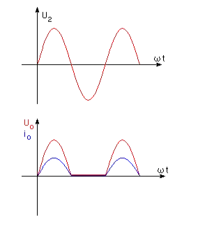
Characteristics of half-wave bridge rectifier
The full-wave bridge rectifier circuit, commonly referred to as the Graetz bridge, is depicted in the figure below.
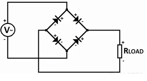
In the operational context of the full-wave bridge rectifier circuit, the current flow follows a specific pattern as illustrated in the diagram (depicted in red). Two red diodes are forward biased, allowing them to conduct current, while the other two diodes are reverse biased, impeding current flow. The sequence of events unfolds with current emanating from the power supply through the first red diode. Subsequently, it traverses the load, passing through the first red diode. Upon completing the load circuit, the current then courses through the second red diode before returning to the power supply.
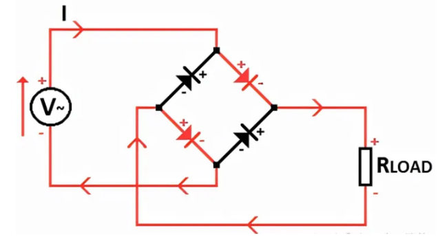
This orchestrated flow ensures that during each half-cycle of the input alternating current, there is a path for current to flow through the load. The synergy of forward and reverse-biased diodes facilitates the conversion of alternating current into a smoother, more continuous unidirectional flow. The full-wave bridge rectifier circuit, exemplified by the Graetz bridge, stands as a pivotal component in rectification systems, contributing to the efficient conversion of alternating current to direct current.
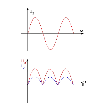
Time characteristic diagram of full-wave rectifier circuit
Three-phase diode bridge rectifier circuits, often referred to as full-wave bridge rectifier Diablos, find versatile application in any three-phase voltage circuit. One notable advantage of these circuits is the minimal output voltage ripple they exhibit. This characteristic ensures that the power supply efficiently utilizes the circuit's power, contributing to enhanced stability and performance. Moreover, three-phase bridge rectifier circuits typically incorporate the capability to control the output current, providing an added dimension of flexibility in their operational parameters.
A visual representation of the three-phase rectifier circuit is presented in the schematic diagram below, offering insight into the structural composition and configuration of the circuit. This diagram serves as a valuable resource for understanding how the three-phase rectifier circuit is constructed and highlights its potential for optimized power utilization and controlled output current in various three-phase voltage applications.
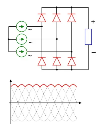
Three-phase rectifier circuit schematic diagram and characteristic diagram
A bridge rectifier typically uses four diodes arranged in a bridge configuration. The arrangement forms a bridge circuit, often referred to as a full-wave bridge rectifier. The four diodes are connected in such a way that they allow the rectification of both halves of the input alternating current (AC) waveform, resulting in a more continuous and smoother unidirectional current at the output. The bridge rectifier configuration is commonly used in various power supply and rectification applications due to its efficiency in converting AC to DC.
In conclusion, rectifier diodes stand as indispensable components in the realm of electronics, bridging the gap between alternating and direct current systems. Their diverse range of uses, from powering everyday devices like mobile phones and laptops to contributing to the stability of industrial power supplies, underscores their significance. With distinct types catering to specific requirements and a set of well-defined characteristics, rectifier diodes provide engineers and electronic enthusiasts with versatile tools to ensure the smooth and efficient conversion of electrical currents.