March 19, 2021
3403
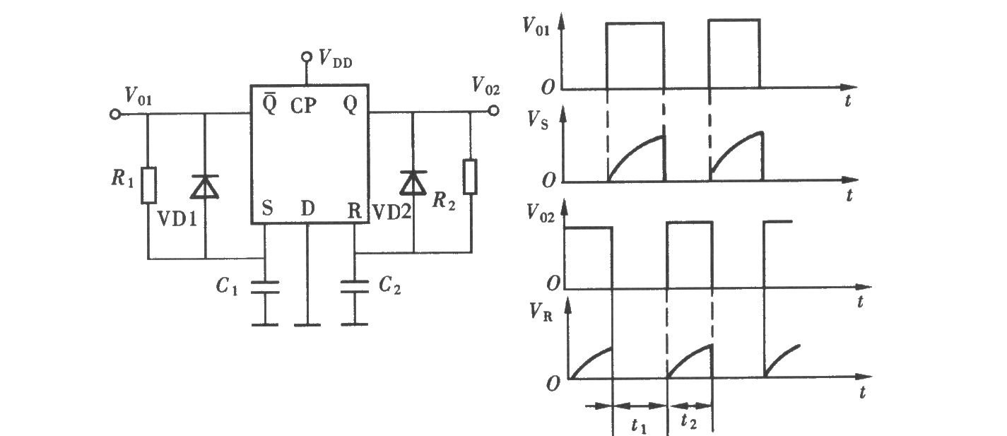
After connecting the RC component to the Q output terminal of the D flip-flop, a monostable flip-flop is formed. A group of RC components are also connected to the Q non-output terminal to form an astable circuit, that is, a multivibrator. The circuit composition is shown in the figure.

Principle of Oscillation:
When the switching signal reaches a low level, a rising edge pulse will appear at the output terminal of the NOR gate, which is added to the CP terminal.
At this time, the first flip-flop enters a transient stable state, Q1 turns to a high level, and C1 is charged through R1. As the voltage of C1 rises, the R terminal is triggered to reset it, and Q1 turns to low level. /Q1 turns to a high level, and a rising edge pulse is applied to the CP end of the second flip-flop.
At this time, the second flip-flop enters a transient stable state, Q2 turns to a high level, and C2 is charged through R2. As the voltage of C2 rises, the R terminal is triggered to reset it, and Q2 turns to a low level. After the NOR gate, a rising edge pulse is applied to the CP terminal of the first flip-flop.
This cycle forms an oscillation, and a square wave is output at Q1 and Q2.
VD1 and VD2 provide fast discharge circuits of C1 and C2 respectively, and the duty cycle is adjusted by R1C1 and R2C2.
In addition, a flip-flop can also constitute an oscillator.