December 14, 2020
3935
Step 1: Parts list
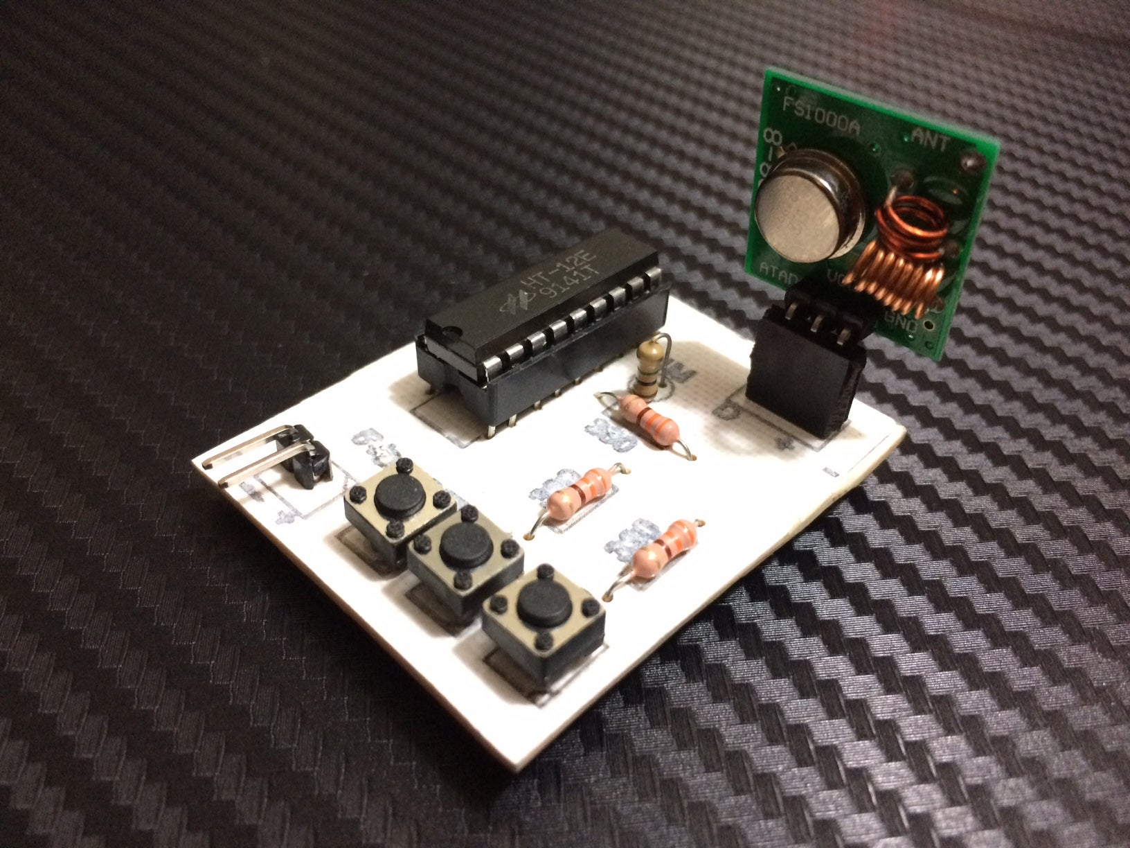
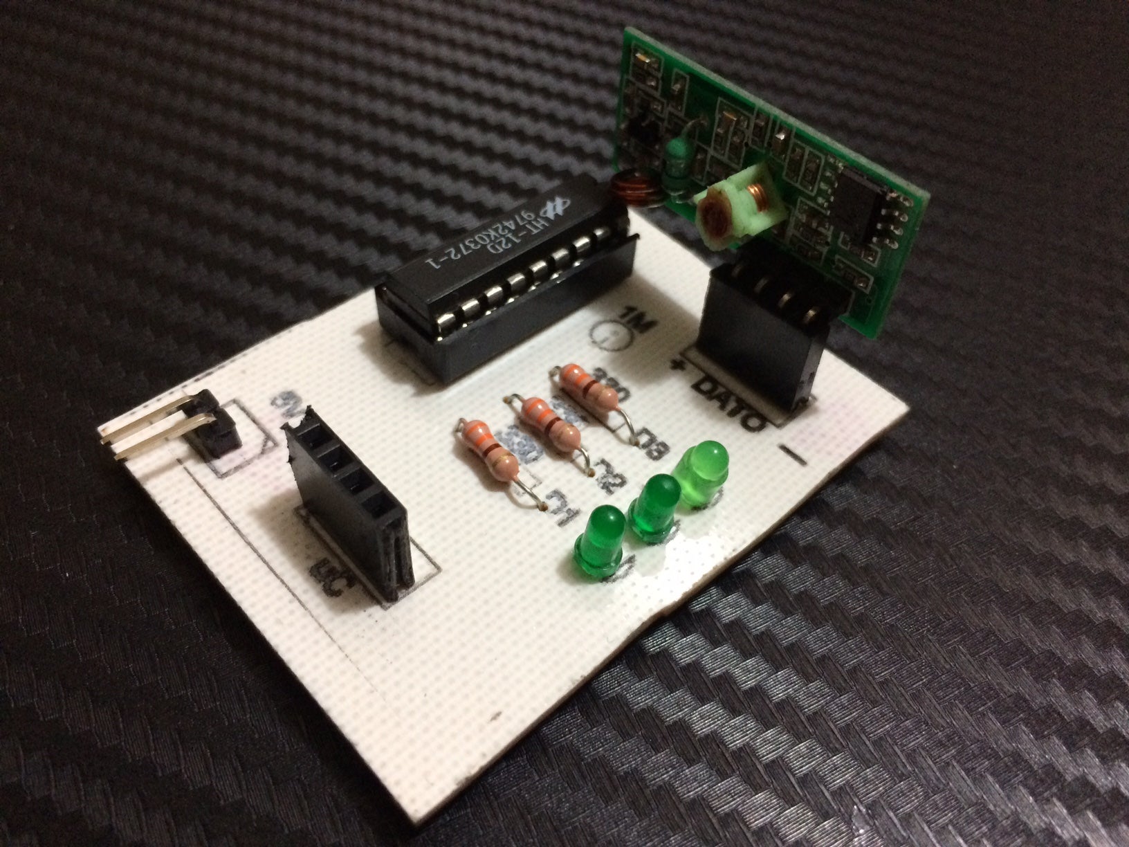
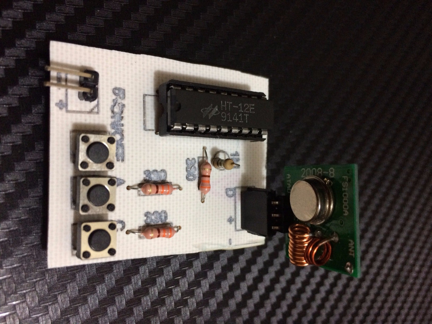
RF transmitter and RF receiver 433 Mhz
3 buttons
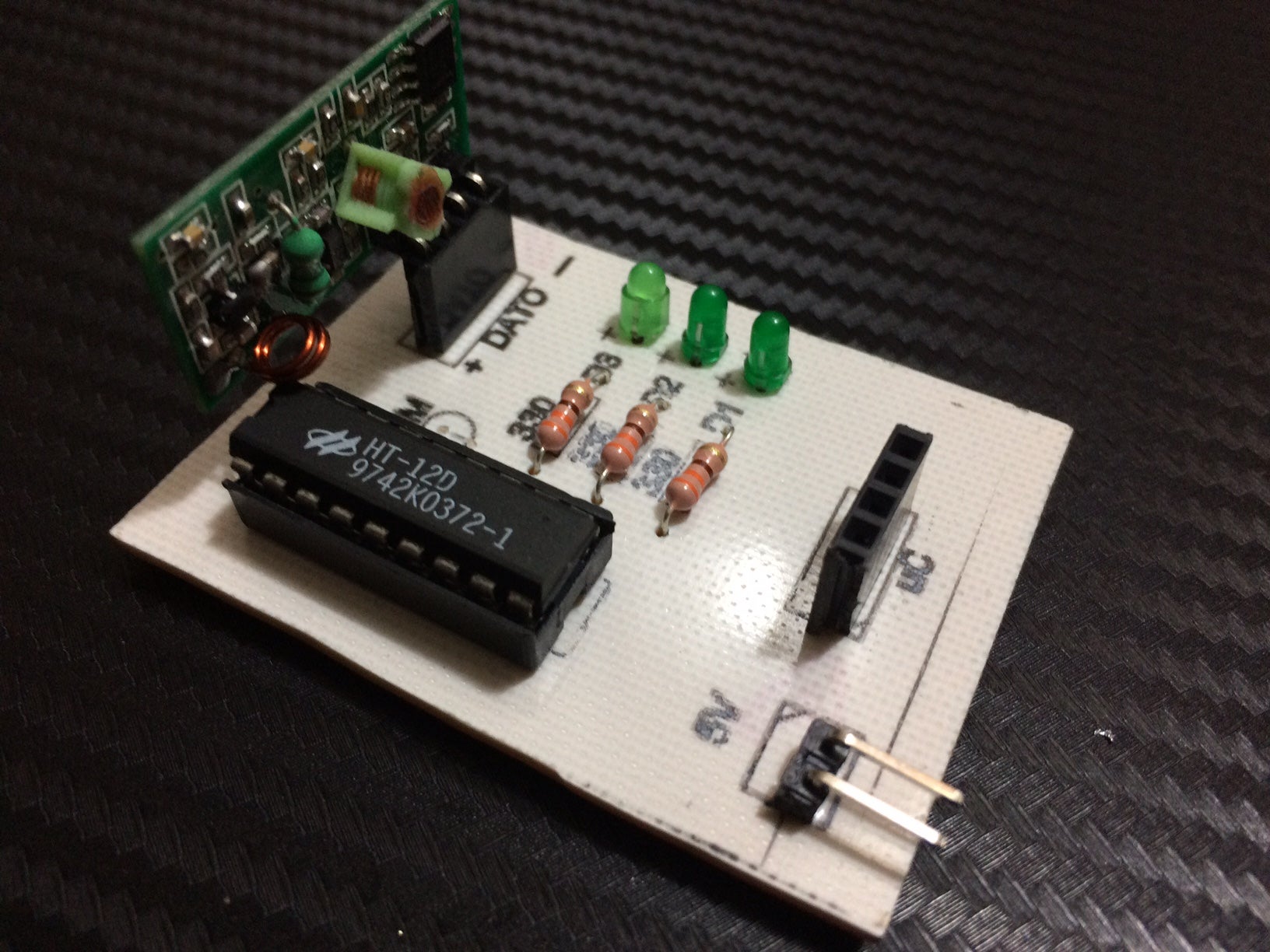
IC HT12D
IC HT12E
Hearders
3 resistance values (100 to 330) ohm
3 LED any color 3mm diameter (miniature)
1 megohm resistor for the IC of the transmitter (important)
Acceptor’s 51 K or very, very new resistance value (important)
Step 2: Work description:
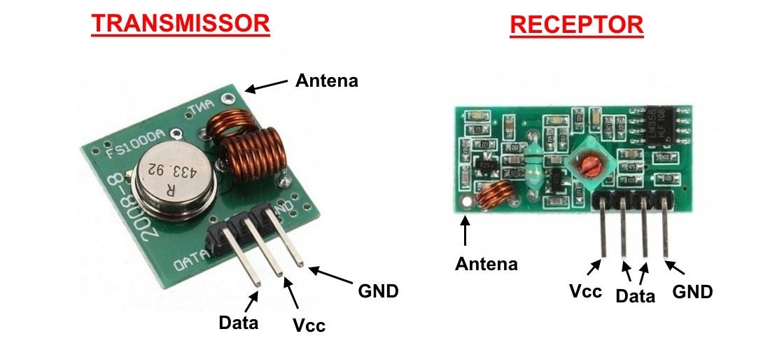
A radio frequency transmitter with a good antenna can transmit data up to 500 ft (outdoor unobstructed)
The working voltage of the radio frequency transmitter is: (3.3v-5 v)
The working voltage of the radio frequency receiver is: (5v-9v).
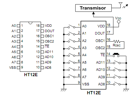
HT12E pin (encoder)
Pins 1-8: The setting of the receiving direction, which means that it can individually change the communication address if necessary
9. Connect VSS to GND
10-13. The AD in this pin is used to transmit 3 bits of data (in our case, the receiver)
14. Transmission enable, you can connect this pin to GND
15-16. In this port, it is very important to put a "oscillation resistance", use 1M ohm value
17. This pin must be connected to the data pin of our 433 Mhz RF transmitter.
18. This pin is connected to VCC or the positive terminal of our power supply or battery
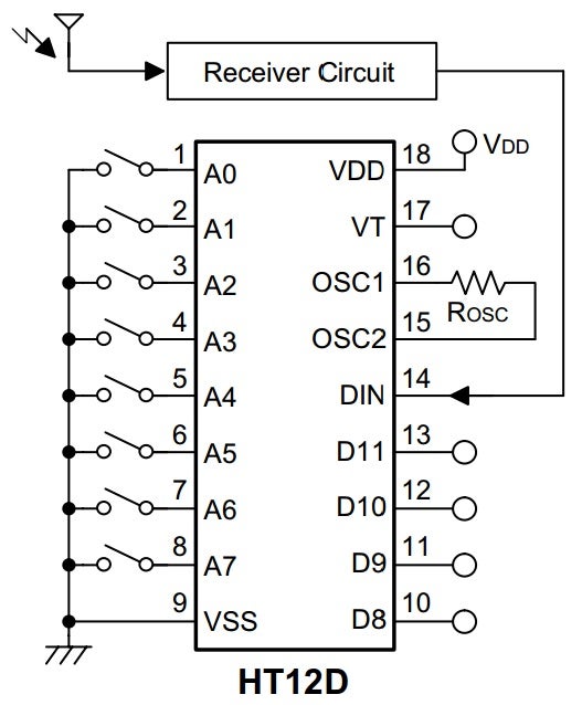
PINOUT (decoder) of HT12D
1-8. Connect to gnd to enable communication with HT12E
9. VSS This pin goes to GND.
10-13. The "AD" IC uses this pin as the output data sent by the transmitter, in our example, the LED for indicating the received information and the direct output for connecting a relay or anything you want.
14. "DIN" This pin is connected to the DATA of our 433 Mhz RF receiver.
15-16. Connect a resistance value of 51 k ohm or very close value to this port, such as 50 k or 52 k (important note: if your circuit has not changed, please do not change the value of this resistance to work)
17. Unrelated.
18. This pin goes to VCC or our positive power supply.
Step 3: Download the circuit
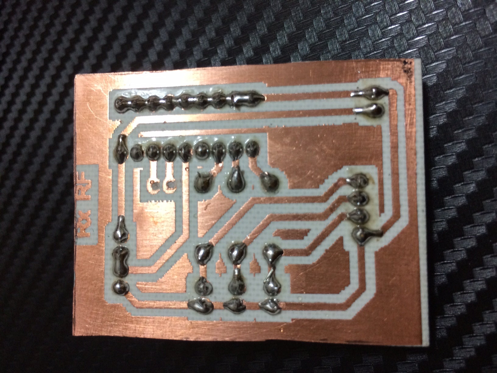
Like all my tutorials, you can download the PDF circuit ready to print and make our
In order to save money and worksheets, the tx and rx circuits are on the same sheet of paper, and the screen components are also used to guide and produce more professional final works!
Step 4: Working video
