May 27, 2021
2732
Increasingly stringent CO2 emission standards and changing public and corporate opinions are accelerating the global development of electric vehicles (EV). This brings huge growth space for on-board chargers (OBC) in the next few years. According to recent trends, the compound annual growth rate (CAGR (TAM)) is estimated to reach 37.6% or higher by 2024. For cars where OBC modules are being designed around the world, improving system energy efficiency or defining a highly reliable new topology has become an imminent challenge.
The simple power factor correction (PFC) topology (Figure 1) for single-phase input AC systems is a traditional single-channel boost converter. The program includes a diode full bridge for input AC rectification and a PFC controller to increase the power factor of the load, thereby improving energy efficiency and reducing the harmonics imposed on the AC input power supply. The advantages of this popular PFC boost topology are simple design, low implementation cost and reliable performance. However, the conduction loss of the diode bridge rectifier is inevitable, and this will not support the two-way operation of the vehicle to provide electrical energy to the AC grid. The use of multi-channel interleaved traditional boost converters and multiple iterations of the boost circuit can improve certain system performance parameters, but the input diode bridge cannot be omitted.
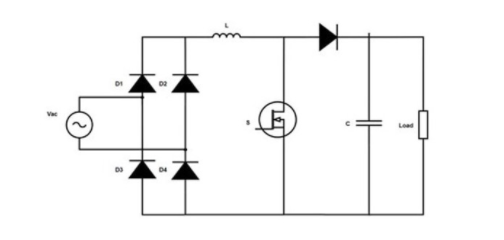
Figure 1: Traditional PFC
The simulation data (Figure 2) shows that in the PFC block, the power loss of the input diode bridge is larger than the loss of all other components.
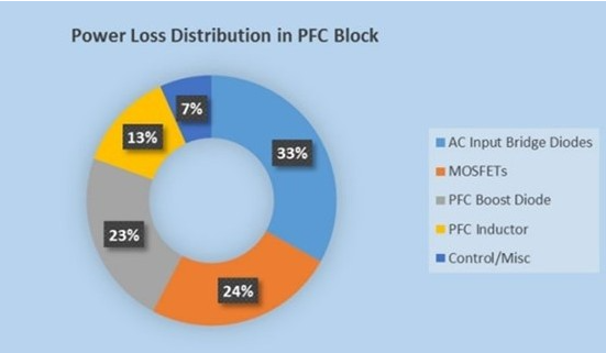
Figure 2: Power loss distribution in PFC
In order to improve the energy efficiency of the OBC system, people have studied different PFC topologies, including traditional PFC, semi-bridgeless PFC, bidirectional bridgeless PFC and totem pole bridgeless PFC. Among them, the totem pole PFC (Figure 3) is popular because of its reduced number of components, reduced conduction loss, and high energy efficiency.
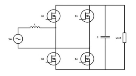
Figure 3: Bridgeless totem pole PFC
Traditional silicon (Si) MOSFETs are difficult to operate in continuous conduction mode (CCM) in the totem-pole PFC topology because the body diode has poor reverse recovery characteristics. Silicon Carbide (SiC) MOSFET adopts a brand-new technology and has better switching performance than Si MOSFET, extremely small reverse recovery time, low on-resistance RDS(on) and higher reliability. In addition, the compact chip size ensures low capacitance and low gate charge (QG) of the device.
Another challenge in designing OBC is that the space allocated for modules in the vehicle is limited. As power requirements and battery voltages continue to increase, it is becoming more and more difficult to design an OBC that can not only meet the mechanical size requirements but also provide the required output power. With the current technology used for OBC, engineers have to make trade-offs between power, size, and energy efficiency, and SiC is breaking through these design barriers. Engineers use SiC with a higher switching frequency, can use smaller inductors, and still meet the same inductor ripple current requirements as before.
The benefits of using SiC MOSFETs in OBC systems are the ability to switch at a higher frequency, higher power density, higher energy efficiency, improved EMI performance, and reduced system size. Today, SiC is widely used, and engineers can use totem pole PFC in their designs to improve performance.
The latest OBC evaluation board with 6.6 kW totem pole PFC released by ON Semiconductor Solution Center provides a reference design for the multi-channel interleaved bridgeless totem pole PFC topology. The design includes an isolated high-current, high-efficiency IGBT driver (NCV57000DWR2G) and two high-performance SiC MOSFETs (NVHL060N090SC1) in each high-speed branch. In addition, the low-speed branch adopts two 650 V N-channel power MOSFETs SUPERFET®III (NVHL025N65S3) controlled by a monolithic high-side and low-side gate driver IC (FAN7191_F085).
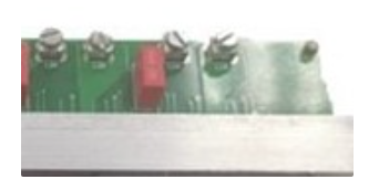
Figure 4: 6.6 kW staggered totem pole PFC evaluation board
Using these high-performance SiC MOSFET configurations in the totem pole topology, the system energy efficiency reaches 97% (typical value). The design includes hardware over-current protection (OCP), hardware over-voltage protection (OVP) and auxiliary power distribution system (non-isolated), which can supply power to each circuit on the PFC board and control board without other DC sources. Flexible control interface can adapt to various control boards.
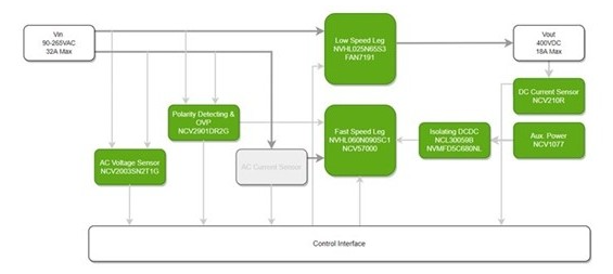
Figure 5: Block diagram of 6.6 kW staggered totem pole PFC evaluation board