November 25, 2020
2886
In order to meet the increasingly stringent size requirements of compact electronic devices, integrated circuit (IC) designers integrate external components into the device to minimize the number of external components. In the construction of various circuits required for all electronic devices, reducing the size of DC-DC converters is also extremely challenging, because they are ubiquitous (all devices require power), and power designers usually face such a reality, That is, reducing the solution size often has a negative impact on performance.
For example, one method that can significantly save PCB area is to use a single-chip DC-DC converter that integrates carefully selected power switching devices into the IC package, thereby reducing the required external components to a small number of Source device. In many cases, the compact design will eventually bring undesirable results compared with the external power switch controller design, that is, increased power loss in a smaller space, resulting in higher temperature rise. In order to avoid troubles caused by the level of heat generated, choosing a suitable monolithic DC-DC converter is essential to design a compact and efficient power system.
1. 2MHz single chip 4-switch buck-boost DC-DC converter and LED driver
LT3942 is one of ADI's very common single-chip buck-boost regulator ICs. The boost-buck converter can cope with the challenge of creating a flexible and compact DC-DC converter solution without sacrificing performance. The LT3942 integrates four 40 V/2 A power switches, two gate driver bootstrap diodes and all of its control and driver circuits into a small 4 mm × 5 mm QFN package. With the ability to operate at a switching frequency of up to 2 MHz, it can minimize the size of external components, save PCB space, and provide high-bandwidth operating performance for various DC-DC converters.
The LT3942 has the same peak current mode control scheme as the LT8390A/LT8391A series of buck-boost controller ICs, and is capable of 2-switch boost, 4-switch buck-boost (boost-buck) and 2-switch buck Seamless conversion between working modes. The converter monitors and compares its input and output voltages to determine the correct operating mode. When the ratio of PVIN:PVOUT changes and forces the converter to switch modes, the LT3942 maintains a voltage stabilizing effect and can intelligently switch control between switch pairs.
In addition to regulating the output voltage through a variety of PVIN:PVOUT combinations, the LT3942 can also be configured to regulate input or output current for constant current regulation applications. The current monitoring feedback from the ISMON pin provides a buffered voltage output proportional to the measured current, allowing the connected circuit to monitor the measured current level. This ability to regulate current or voltage makes the LT3942 very suitable for use as an LED driver, compact battery charger, miniature solar panel-powered converter, or general-purpose regulator.
2. 14 V, 1 A LED driver
Figure 1 shows a complete evaluation circuit based on the LT3942 compact LED driver. This solution can provide 1 A of current for a string of four (up to 14 V) white LEDs connected in series. The input voltage range of maximum power output is 7 V to 36 V, and can be reduced to 4 V at low operating current, which is very suitable for unregulated automotive input power. The operating switching frequency of the LT3942 in this solution is 2 MHz, so relatively small inductors and capacitors can be used. Therefore, the complete LED driver solution is suitable for a PCB size of 15 mm × 15 mm, and all components are located on the same side of the circuit board (including IC).

Figure 1. This LT3942-based demonstration circuit (DC2404A) shows a high-performance, compact DC-DC regulator solution specifically designed to drive LEDs in this situation.
The solution also has high bandwidth performance and can quickly adjust the output current. When working in step-down mode, the LT3942 uses an external PWM source to perform 100Hz flicker-free dimming of the LED, thereby achieving a dimming ratio of up to 5000:1. If there is no external PWM source, you can also use its internal PWM dimming function to achieve LT3942 dimming. Internal dimming provides up to 128:1 dimming function, without any external PWM signal source, only a resistor can set the dimming frequency, and a DC voltage to control the duty cycle of the output current. Like most ADI Power's LED drivers, the LT3942 also has an analog dimming function, which can provide up to 20:1 analog dimming by applying a DC voltage on the CTRL pin. Analog and PWM dimming can be used in combination to achieve a higher effective dimming ratio than either method alone.
3. Spread spectrum is used to reduce EMI peak
To help create a low-noise DC-DC converter system, LT3942 has a built-in optional spread spectrum (SSFM) function. Once SSFM is enabled, it will sweep the switching frequency from the value set by the RT resistor to an additional switching frequency of up to 25%. This scanning action can disperse the radiation caused by the switch in a wide spectrum, instead of concentrating these radiation in a narrow band, thereby reducing the overall EMI peak. When SSFM is used in combination with input and output EMI filters, it helps to reduce EMI in a wide frequency range, making it easier to design systems that meet emission standards.
4. 12 V, 1 A regulator
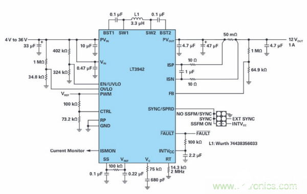
The LT3942 is not limited to driving LEDs. It is a powerful and compact regulator, very suitable for solving the problem of stable output from a wide range of unregulated power supplies. The 12 V, 1 A regulator design shown in Figure 4 is similar to the 14 W LED driver solution in Figure 2, but with some minor changes. Like LED driver applications, regulators can maintain output regulation over a wide input voltage range, provide full output power at voltages as low as 7 V, and maintain low output at voltages as low as 4 V Power work.
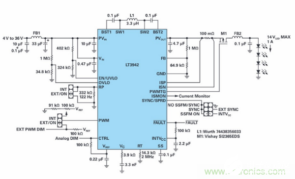
Figure 2. DC2404A uses LT3942 to create a compact 14 W LED driver application that can provide stable output current over a wide input range.
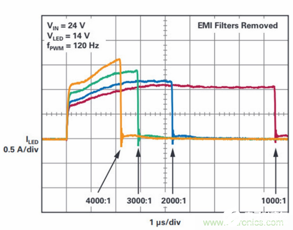
Figure 3. The high bandwidth performance of LT3942 helps LED lighting applications to achieve high ratio PWM dimming in a wide dynamic brightness range. Without EMI filter, DC2404A can achieve up to 4000:1 dimming at 120 Hz, and can achieve up to 5000:1 dimming at 100 Hz.
The efficiency curve in Figure 4 shows that even when the operating switching frequency is 2 MHz, the LT394212 V regulator has an excellent peak efficiency close to 95%, while the efficiency in most of its input voltage range is 85% or higher. Even if one-tenth of its total output power is used for its output power supply, it can maintain an efficiency of more than 80%, which shows that the device can still operate efficiently under light load conditions.
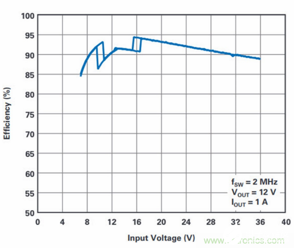
(a). Input Voltage Efficiency Sweep.
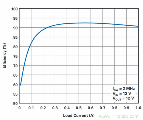
(b). Load Current Efficiency Sweep.
Figure 4. The LT3942 configured as a 12 W regulator has excellent voltage regulation and load efficiency characteristics over a wide input range.
The LT3942's current detection and control features make it not only suitable for LED dimming control, but also excellent work in other situations that require voltage regulation and current control. When the sense resistor is configured at the output, the LT3942 can be easily configured as a compact constant current and constant voltage battery charger. For applications with strict input current limitation, such as circuits powered by small batteries, capacitor banks, or photovoltaic cells, the monitoring resistor can be moved to the input side of the regulator to provide input current limitation and monitoring for the system. The LT3942 can be seamlessly converted from CC mode to CV mode (and vice versa), ensuring that the input and/or output are always stable.
5 The car sequentially lights up turn signals and decorative lighting
Animated sequential turn signal lights, which are common in new luxury cars and high-performance cars, are rapidly spreading, gradually replacing traditional flashing indicators. Early implementations of sequential lighting of turn signals used multiple buck converters or linear regulators to supply power to the LEDs in the turn signal light group, resulting in a complex, relatively inefficient, and too large solution, which greatly restricted the application of lighting design field. Reducing the number of power ICs required and using a single high-efficiency device are obvious ways to expand the range of choices for lighting designers.
The components required for a single converter solution can maintain the output of the string voltage of various LED combinations (from all LEDs to single LEDs, and various other combinations in between) in the lighting design. adjust. As the animation light changes in various configurations of connected LEDs, the input voltage will be higher, lower or equal to the output voltage. This type of application requires a boost-buck converter that can intelligently select operating modes and seamlessly switch between operating modes while maintaining output regulation. The LT3942's buck-boost topology and high-bandwidth performance make it easy to manipulate these changes without glitches.
The sequential lighting turn signal design shown in Figure 5 uses LT3942 to power eight LEDs from a car battery with a current of 330mA, and can be selected as a string of amber LEDs (for turn signal operation) and a string of white LEDs (used in Japan). Intermediate running lights) or other decorative lighting (used in headlight/taillight design).
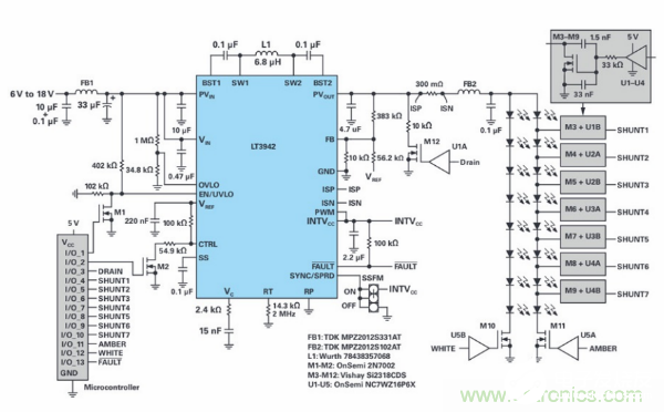
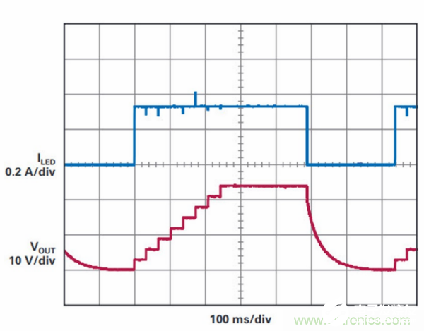
Figure 5. In a sequential lighting turn signal application, one LED is turned on at a time, which forces the DC-DC converter to quickly adapt to the new PVIN:PVOUT combination. This is not a problem for the LT3942, because it can seamlessly switch from boost, buck-boost, and buck operating modes during the sequential lighting steering mode, thus ensuring that a stable LED current is maintained in various modes.
The microcontroller acts as an interface between the turn signal input by the user and the lighting system. This allows the lighting designer (or the end user, if needed) to fully control all the timing and signals required to perform the LED animation sequence lighting, and can control which color LED string is powered at any given time.
In this design, during the sequential lighting mode, one turn signal LED is introduced to the light string at a time to generate a turn signal. When the LED is added to the light string by the microcontroller, the LT3942 maintains the adjustment of the output current to maintain consistent light brightness. After all LEDs are lit, LT3942 stops switching and pulls down the output voltage to make the converter ready for the next sequential lighting cycle. When the turn signal is not used, the microcontroller reconnects to the decorative lighting LED string and continues to wait for the turn signal user input, which combines the two lighting functions into one LED driver solution.
6 Summary
Electronic equipment forces engineers to continuously seek smaller integrated devices to meet the growing demand for space constraints. The LT3942 single-chip buck-boost converter and LED driver integrate many space-saving features to solve space-constrained electrical design challenges without sacrificing performance. Its single-chip design and 2 MHz operating switching frequency reduce the size of the solution, making it suitable for compact PCB designs. The device is highly flexible and can be used as a constant current regulator or a constant voltage regulator, suitable for a variety of applications.
For designs that require a low-noise power supply to meet strict EMI requirements, the SSFM function of LT3942 helps reduce conducted emissions and electromagnetic radiation disturbances, and its convenient IC package pin arrangement can achieve a compact switch thermal loop. These features, along with the wide input range, simplify the work of designers when they face compact power supply requirements.
LT3942
● 4-switch single inductor architecture can make VIN greater than, less than or equal to VOUT
● Proprietary peak buck/peak boost current mode
● 3V to 36V input voltage range
● 0V to 36V output voltage range
● ±1.5% output voltage adjustment
● ±3% LED current adjustment
● 5000:1 external and 128:1 internal PWM dimming
● Rail-to-rail LED current detection and monitoring output
● Open and short LED protection and fault report
● 300kHz to 2MHz fixed switching frequency and external frequency synchronization
● Flicker-free spread spectrum can reduce EMI
● Use 28-pin QFN (4mm × 5mm) package
