May 19, 2021
2195
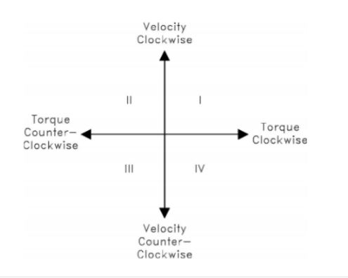
This article discusses torque control and speed control in detail. In a speed controller, the speed (or speed) of the motor is controlled. There is an element that can detect speed, whether it is a tachometer or some kind of encoder. This monitor element provides feedback to the speed controller to increase or decrease the speed. The speed controller controls the speed of the motor by increasing or decreasing the voltage applied to the motor. In the PWM controller, the proportional voltage can be controlled by controlling the PWM duty cycle. After voltage is applied, current will flow through the motor windings. This current provides torque to rotate the motor. The current is not directly controlled, but is controlled by the applied voltage. The speed controller can control the clockwise or counterclockwise speed by applying positive or negative voltage. This is called a two-quadrant controller. Clockwise torque in the clockwise direction and counterclockwise torque in the counterclockwise direction.

Figure 1 Four-quadrant control diagram
In systems where the speed remains fairly constant due to the high bandwidth control signal or does not require rapid changes, the speed controller is sufficient. In order to realize a two-quadrant speed control amplifier, it is necessary to understand the PWM period.

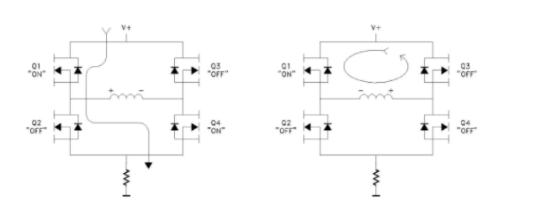
Figure 2 Two quadrant speed control, one PWM cycle
Figure 2 is an example of a typical 2-quadrant speed control. The upper MOSFET switch (Q1 or Q3) is used as a direction control element, and the lower MOSFET switch (Q2 or Q4) performs PWM modulation to control the voltage in the motor windings. When Q1 and Q4 are turned on, the current flows through Q1, through the motor windings, through Q4, and then back through the sense resistor at the bottom of the bridge. When the switch Q4 is off, since the current in the inductor cannot be changed instantaneously, the voltage on the motor windings will be reversed. This is due to the attenuation of the magnetic field. The resulting current will "freewheel" through the body diode of Q3 and return to the top loop. Note that no current flows in the sense resistor. During the "OFF" part of the PWM cycle, no current is detected. The current flowing is not controlled because it will decay in the loop. Depending on the PWM duty cycle, the current may decay back to zero and stay there until the next cycle. Since the current is only viewed during a part of the PWM cycle, this method is not suitable for four-quadrant torque control.