January 06, 2021
2053
Mark Thoren, ADI's PowerbyLinear scientific expert.

Among them:

Or when VREF is 5V and both inputs are grounded, it is about 1.67μA.
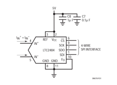
Figure 1: The connection method of LTC2484.
Figure 2 shows how to balance the thermistor to minimize ADC input current. If the reference resistors R1 and R4 are exactly equal, then the input current is zero and no error occurs. If the tolerance of the reference resistor is 1%, then due to the slight drift of the common-mode voltage, the maximum error of the measured resistance is 1.6Ω, which is much smaller than the 1% error of the reference resistor itself. This solution does not require an amplifier, making it very suitable for micro-power applications.
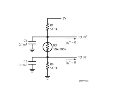
Figure 2: The sensor in the middle
You may need to ground one end of the sensor to reduce the noise picked up, or if the sensor is at the far end, you can simplify wiring. If this circuit is used without buffering, the changing common-mode voltage causes a 3.5kΩ full-scale error in the measured resistance.
Figure 3 shows how to connect an operational amplifier with very low power and very small bandwidth to the LTC2484. For amplifiers with a supply current of 1.5µA, the LT1494 has excellent DC performance specifications, with a maximum offset voltage of 150µV and an open-loop gain of 100,000, but its 2kHz bandwidth makes the device unsuitable for driving conventional incremental accumulation ADCs. Adding a 1kΩ, 0.1µF filter can provide a charge library that supplies the instantaneous sampling current of the LTC2484, thus solving this problem, while the 1kΩ resistor isolates the capacitive load from the LT1494. Don't try to use ordinary incremental accumulation ADC to do so, because in the circuit shown in Figure 3, the sampling current of the ADC with similar performance specifications to the LTC2484 series will produce 1.4mV offset and 0.69mV full-scale error. The balanced input current of the LTC2484 allows these errors to be easily eliminated by placing an identical filter on the IN- terminal.
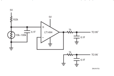
Figure 3: Grounded, buffered sensor
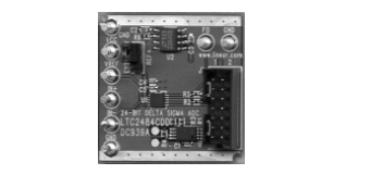
Figure 4: LTC2484 demonstration circuit board
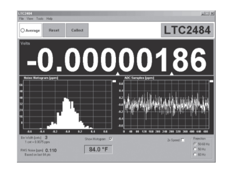
Figure 5: Screenshot of the LTC2484 demo software, with an offset of microvolts and a noise of 600nVRMS