June 21, 2023
4401
Category:
What is LM3915 IC?
LM3915 Datasheet, Pinout and Equivalent Part Numbers.
How Does the LM3915 IC Works?
How to Use LM3915 IC?
LM3914 VS LM3915 VS LM3916 application & uses
The LM3915 is a monolithic integrated circuit that functions as a driver for LEDs or other visual indicators in a bar graph or dot mode display. The IC is designed to display the level of an analog voltage input signal, with each output of the IC driving one LED or other indicator.
A VU meter is used to display the level of an audio signal, typically in decibels (dB), and is an essential tool in audio mixing and recording applications.
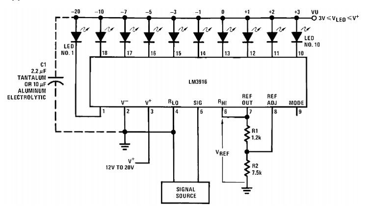
To use the LM3915 as a VU meter, an audio signal is applied to the IN pin, and the display range is set using external resistors connected to the RLO and RHI pins. The voltage reference can be adjusted using a potentiometer connected to the REF ADJ pin.
A VU meter based on the LM3915 will have a logarithmic scaling of the display range to match the way that human hearing perceives changes in sound level. The output pins of the LM3915 will drive a series of LEDs or other visual indicators, with each LED representing a specific dB level of the audio signal.
Number of Outputs | 10 (can drive up to 10 LEDs or LED bar graph displays) |
Voltage Range | Typically operates from 3V to 25V |
Input Signal Range | 0V to the supply voltage (V+) |
Logarithmic Scale | Provides a logarithmic display scale for more intuitive voltage level representation |
Built-in Reference Voltage | The IC has a built-in voltage reference for accurate voltage level measurement |
Dot Mode and Bar Mode | Offers both dot mode and bar mode displays |
Adjustable Brightness | Allows for adjustable brightness control of the LEDs |
Power Supply Voltage | Typically powered by a single positive power supply voltage (V+) |
Package | Available in various package types, such as PDIP, SOIC, and TSSOP |
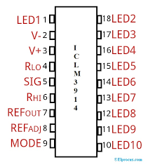
The LM3915 IC has a total of 18 pins.
Pin Number | Pin Name | Description |
1 | V+ | Positive power supply voltage input. |
2 | RHI | External resistor connection for the high-level reference voltage. |
3 | RLO | External resistor connection for the low-level reference voltage. |
4 | REFOUT | Reference voltage output. |
5 | REFADJ | Reference voltage adjustment pin. |
6 | GND | Ground (0V) connection. |
7 | MODE | Mode selection pin for dot mode or bar mode. |
8 | D9 | Output pin for LED 9. |
9 | D8 | Output pin for LED 8. |
10 | D7 | Output pin for LED 7. |
11 | D6 | Output pin for LED 6. |
12 | D5 | Output pin for LED 5. |
13 | D4 | Output pin for LED 4. |
14 | D3 | Output pin for LED 3. |
15 | D2 | Output pin for LED 2. |
16 | D1 | Output pin for LED 1. |
17 | LED 10 | Output pin for LED 10. |
18 | LED 9 | Output pin for LED 9. |
The LM3914 is another monolithic integrated circuit that is similar to the LM3915. Like the LM3915, the LM3914 is designed to drive a series of LEDs or other visual indicators to display the level of an analog voltage input signal in a bar graph or dot mode display.

Pin Number | Pin Name | Function |
1 | V+ | Positive supply voltage input for the IC. |
2 | Signal Input | Analog signal input for the IC. |
3 | GND | Ground or negative power supply voltage input for the IC. |
4 | Mode Select | Selects the mode of operation for the IC, either bar graph or dot mode. |
5 | RHI | Sets the reference voltage for the high end of the display range. |
6 | RLO | Sets the reference voltage for the low end of the display range. |
7 | REF ADJ | Adjusts the internal reference voltage of the IC. |
8 | OE | Enables or disables the outputs of the IC. |
9-18 | Output Pins | Drive the LEDs or other visual indicators in a bar graph or dot mode display. |
LM3914 has fewer output pins, with only 10 outputs compared to the 18 outputs of the LM3915. The LM3914 can still drive up to 30mA of current per output pin, and the display range can be set using external resistors.
The LM3914 also has some additional features compared to the LM3915, including the ability to drive a DOT mode display directly, and a shutdown pin that allows the IC to be turned off when not in use to save power.
LM3916
Im3916 is a monolithic IC that senses analog voltage levels (especially audio signals) and drives ten LEDs in dot mode or bar graph mode. It is a multifunction IC. the most popular application for the Lm3916 is VU meters. the Im3916 chip contains an adjustable reference voltage source and an accurate ten-step voltage divider. The high impedance input buffer accepts signals within 0V~Vcc-1.5V. In addition, it does not require protection against ±35V inputs. The input buffer drives independent comparators with 10 reference precision dividers. Accuracy is typically better than 0.2dB.
Audio applications for the LM3916 include average or peak level indicators and power meters. Replacing conventional meters with LED bar graphs produces a more responsive and rugged display with higher visibility and retains the ease of understanding of analog displays.

Lm3916 dotbar display datasheet
The LM3915 is a voltage level indicator and driver IC that is commonly used to display analog signal levels on a series of LEDs or LED bar graph displays. It works by converting an input voltage into a corresponding visual representation on the LEDs.
The LM3915 works by comparing the input voltage to a reference voltage and generating a signal that activates the appropriate LED or indicator. The IC has an internal voltage reference that can be adjusted to set the display range, and a choice between logarithmic and linear scaling of the display range.
The LM3915 has 10 outputs that can drive up to 30mA of current each, allowing it to drive up to 10 LEDs or other visual indicators. The output pins are arranged in a linear or logarithmic order depending on the selected scaling mode.
In bar graph mode, the output pins of the LM3915 activate LEDs progressively as the input voltage increases, with the number of activated LEDs indicating the level of the input voltage relative to the display range. In dot mode, only one LED is activated at a time, with the LED corresponding to the highest output pin that is activated.
To use the LM3915, an analog voltage input signal is applied to the IN pin, and the display range is set using external resistors connected to the RLO and RHI pins. The voltage reference can be adjusted using a potentiometer connected to the REF ADJ pin.
Here are the components required for using Lm3915:
Capacitors (optional)
LEDs or other visual indicators
Power supply
Analog signal source
IC LM3915 is a dotbar driver, which is offers a simple and effective solution for visualizing analog signal levels with LEDs or LED bar graphs.